
August 12, 2023
04 Hello Raster
In our previous post about Compute Rasterization, we rendered all geometry without view culling and LODs. Let’s now utilize the same Compute rasterization shader and combine it with the Hierarchical LOD Graphs from the previous example. Using 32-bit atomics will help us ensure the application’s compatibility with mobile devices. The rasterization shader will not be perfectly optimal. It will interpolate attributes and calculate color in exactly the same way as the Mesh and Fragment shader. Outputting a single triangle index is significantly faster, and 64-bit atomics may offer an additional performance boost. Therefore, if necessary, the CS performance results can be improved.
The Task shader will be replaced with a Compute shader, and instead of providing payload data for the Mesh shader, we will now write the combined instance and geometry indices into an SSBO buffer. Everything else remains exactly the same.
// Mesh Shader
[[branch]] if(is_visible) {
    int index = atomicIncrement(num_geometries);
    [[branch]] if(index < MAX_GEOMETRIES) OUT.geometries[index] = geometry_index;
}
// Compute Shader
[[branch]] if(is_visible) {
    uint index = atomicIncrement(indirect_buffer[0]);
    batch_buffer[index] = (group_id << 16u) | geometry_index;
}
The Indirect and the Batch buffers are the input of the rasterization shader, which processes a triangle per thread:
// dispatch raster kernel
compute.setKernel(raster_kernel);
compute.setUniform(0, common_parameters);
compute.setStorageBuffers(0, {
    instances_buffer,
    geometries_buffer,
    batch_buffer,
    vertex_buffer,
    index_buffer,
});
compute.setSurfaceTextures(0, {
    depth_surface,
    color_surface,
});
compute.setIndirectBuffer(indirect_buffer);
compute.dispatchIndirect();
This Compute shader performs the same task as both the Mesh and Fragment shaders combined. Rather than generating triangles for the Fragment shader, we directly rasterize them into textures or buffers. This approach saves a significant amount of GPU bandwidth and eliminates the need for triangle binning on tiled architectures:
layout(local_size_x = GROUP_SIZE) in;

layout(std430, binding = 1) readonly buffer InstancesBuffer { vec4 instances_buffer[]; };
layout(std430, binding = 2) readonly buffer GeometriesBuffer { GeometryParameters geometries_buffer[]; };
layout(std430, binding = 3) readonly buffer RasterBuffer { uint batch_buffer[]; };
layout(std430, binding = 4) readonly buffer VerticesBuffer { Vertex vertices_buffer[]; };
layout(std430, binding = 5) readonly buffer IndicesBuffer { uint indices_buffer[]; };

layout(std430, binding = 6) buffer DepthBuffer { uint depth_buffer[]; };
layout(binding = 0, set = 1, r32ui) uniform uimage2D color_surface;

shared vec4 transform[3];
shared uint num_vertices;
shared uint base_vertex;
shared uint num_primitives;
shared uint base_primitive;

shared vec3 positions[MAX_VERTICES];
shared vec3 directions[MAX_VERTICES];
shared vec3 normals[MAX_VERTICES];

shared vec3 geometry_color;
shared float split_position;

/*
 */
void raster(uint i0, uint i1, uint i2) {

    // clip triangle
    vec3 p0 = positions[i0];
    vec3 p1 = positions[i1];
    vec3 p2 = positions[i2];
    [[branch]] if(p0.z < 0.0f || p1.z < 0.0f || p2.z < 0.0f) return;

    // backface culling
    vec3 p10 = p1 - p0;
    vec3 p20 = p2 - p0;
    float det = p20.x * p10.y - p20.y * p10.x;
    #if CLAY_VK
        [[branch]] if(det <= 0.0f) return;
    #else
        [[branch]] if(det >= 0.0f) return;
    #endif

    // triangle rect
    float x0 = min(min(p0.x, p1.x), p2.x);
    float y0 = min(min(p0.y, p1.y), p2.y);
    float x1 = ceil(max(max(p0.x, p1.x), p2.x));
    float y1 = ceil(max(max(p0.y, p1.y), p2.y));
    [[branch]] if(x1 - floor(x0) < 2.0f || y1 - floor(y0) < 2.0f) return;
    x0 = floor(x0 + 0.5f);
    y0 = floor(y0 + 0.5f);

    // viewport cull
    [[branch]] if(x1 < 0.0f || y1 < 0.0f || x0 >= surface_width || y0 >= surface_height) return;
    x0 = max(x0, 0.0f); x1 = min(x1, surface_width);
    y0 = max(y0, 0.0f); y1 = min(y1, surface_height);

    // triangle area
    float area = (x1 - x0) * (y1 - y0);
    [[branch]] if(area == 0.0f) return;

    // triangle parameters
    float idet = 1.0f / det;
    vec2 dx = vec2(-p20.y, p10.y) * idet;
    vec2 dy = vec2(p20.x, -p10.x) * idet;
    vec2 texcoord_x = dx * (x0 - p0.x);
    vec2 texcoord_y = dy * (y0 - p0.y);

    vec3 d0 = directions[i0];
    vec3 d10 = directions[i1] - d0;
    vec3 d20 = directions[i2] - d0;

    vec3 n0 = normals[i0];
    vec3 n10 = normals[i1] - n0;
    vec3 n20 = normals[i2] - n0;

    for(float y = y0; y < y1; y += 1.0f) {
        vec2 texcoord = texcoord_x + texcoord_y;
        for(float x = x0; x < x1; x += 1.0f) {
            [[branch]] if(texcoord.x > -1e-5f && texcoord.y > -1e-5f && texcoord.x + texcoord.y < 1.0f + 1e-5f) {

                uint z = floatBitsToUint(p10.z * texcoord.x + p20.z * texcoord.y + p0.z);

                // depth test
                uint index = uint(surface_width * y + x);
                uint old_z = atomicMax(depth_buffer[index], z);
                [[branch]] if(old_z < z) {

                    // interpolate attributes
                    vec3 direction = normalize(d10 * texcoord.x + d20 * texcoord.y + d0);
                    vec3 normal = normalize(n10 * texcoord.x + n20 * texcoord.y + n0);

                    // light color
                    float diffuse = clamp(dot(direction, normal), 0.0f, 1.0f);
                    float specular = pow(clamp(dot(reflect(-direction, normal), direction), 0.0f, 1.0f), 16.0f);

                    // pack color
                    vec3 color = (x < split_position) ? vec3(0.75f) : geometry_color;
                    uint c = packUnorm4x8(vec4(color * diffuse + specular, 1.0f));
                    if(abs(x - split_position) < 1.0f) c = 0u;

                    // write color
                    #if CLAY_GLES || CLAY_MTL || CLAY_WG
                        imageStore(color_surface, ivec2(vec2(x, y)), uvec4(c));
                    #else
                        imageAtomicExchange(color_surface, ivec2(vec2(x, y)), c);
                    #endif
                }
            }

            texcoord += dx;
        }

        texcoord_y += dy;
    }
}

/*
 */
void main() {

    uint local_id = gl_LocalInvocationIndex;
    #if CLAY_WG
        uint group_id = gl_WorkGroupID.y * 256u + gl_WorkGroupID.x;
    #else
        uint group_id = gl_WorkGroupID.x;
    #endif

    // mesh parameters
    [[branch]] if(local_id == 0u) {

        // raster group
        uint index = batch_buffer[group_id];

        // instance transform
        uint instance = (index >> 16u) * 3u;
        transform[0] = instances_buffer[instance + 0u];
        transform[1] = instances_buffer[instance + 1u];
        transform[2] = instances_buffer[instance + 2u];

        // geometry parameters
        uint geometry = index & 0xffffu;
        num_vertices = geometries_buffer[geometry].num_vertices;
        base_vertex = geometries_buffer[geometry].base_vertex;
        num_primitives = geometries_buffer[geometry].num_primitives;
        base_primitive = geometries_buffer[geometry].base_primitive;

        // mesh color
        float seed = mod(instance + geometry * 93.7351f, 1024.0f);
        geometry_color = cos(vec3(0.0f, 0.5f, 1.0f) * 3.14f + seed) * 0.5f + 0.5f;

        // split position
        split_position = surface_width * (cos(time) * 0.25f + 0.75f);
    }
    memoryBarrierShared(); barrier();

    // vertices
    [[loop]] for(uint i = local_id; i < num_vertices; i += GROUP_SIZE) {

        // fetch vertex
        uint vertex = base_vertex + i;
        vec4 position = vec4(vertices_buffer[vertex].position.xyz, 1.0f);
        vec3 normal = vertices_buffer[vertex].normal.xyz;

        // transform position
        position = vec4(dot(transform[0], position), dot(transform[1], position), dot(transform[2], position), 1.0f);

        // camera direction
        directions[i] = camera.xyz - position.xyz;

        // normal vector
        normals[i] = vec3(dot(transform[0].xyz, normal), dot(transform[1].xyz, normal), dot(transform[2].xyz, normal));

        // project position
        position = projection * (modelview * position);
        positions[i] = vec3((position.xy / position.w * 0.5f + 0.5f) * vec2(surface_width, surface_height) - 0.5f, position.z / position.w);
    }
    memoryBarrierShared(); barrier();

    // primitives
    [[loop]] for(uint i = local_id; i < num_primitives; i += GROUP_SIZE) {

        // fetch indices
        uint indices = indices_buffer[base_primitive + i];
        uint index_0 = (indices >>  0u) & 0x3ffu;
        uint index_1 = (indices >> 10u) & 0x3ffu;
        uint index_2 = (indices >> 20u) & 0x3ffu;

        // raster triangle
        raster(index_0, index_1, index_2);
    }
}
The Index buffer is now more compact, utilizing 10-bit indices, enabling us to load all triangle indices in a single operation. The same modification has been applied to the Mesh shader example. Additionally, we have reduced the geometry size in the LOD Graph to 128 attributes and 128 primitives (from 256/256). Otherwise, the amount of shared memory limits the performance, and GPU is not fully utilized. It’s possible to increase limits in the case of outputting a triangle index without affecting performance. The two tables show the comparison between CS and MS rendering performance for both 1600×900 and 2560×1440 resolutions:
| 1600×900 | Optimal LOD | Closest LOD | ||
|---|---|---|---|---|
| CS | MS | CS | MS | |
| GeForce 3090 Ti | 780 FPS (1.1 ms) | 240 FPS (4 ms) | 150 FPS (6.6 ms) | 23 FPS (42 ms) |
| GeForce 2080 Ti | 490 FPS (1.6 ms) | 180 FPS (4.9 ms) | 82 FPS (12 ms) | 21 FPS (46 ms) |
| GeForce 3060 M | 195 FPS (4.3 ms) | 81 FPS (11 ms) | 40 FPS (23 ms) | 9 FPS (112 ms) |
| Radeon 6900 XT | 760 FPS (1.1 ms) | 260 FPS (3.2 ms) | 158 FPS (5.8 ms) | 32 FPS (29 ms) |
| Radeon 6700 XT | 370 FPS (2.1 ms) | 140 FPS (6.3 ms) | 82 FPS (11 ms) | 16 FPS (60 ms) |
| Radeon 6600 | 270 FPS (3.0 ms) | 150 FPS (6.3 ms) | 57 FPS (16 ms) | 16 FPS (60 ms) |
| Intel Arc A770 | 450 FPS (1.7 ms) | 109 FPS (9ms) | 80 FPS (12 ms) | 8 FPS (120 ms) |
| Intel Arc A380 | 130 FPS (7.2 ms) | 25 FPS (38 ms) | 20 FPS (47 ms) | 4 FPS (262 ms) |
| Intel Xe 96 | 60 FPS (17 ms) | 9 FPS (103 ms) | ||
| Apple M1 Max | 188 FPS (5 ms) | 60 FPS | 43 FPS (22 ms) | |
| Apple M1 | 50 FPS (19 ms) | 15 FPS | 11 FPS (87 ms) | |
| Apple A15 | 33 FPS (29 ms) | 6 FPS (167 ms) | ||
| Arm Mali-G78 | 22 FPS (43 ms) | 3 FPS (340 ms) | ||
| Adreno 730 | 18 FPS (52 ms) | 3.5 FPS (275 ms) | ||
| 2560×1440 | Optimal LOD | Closest LOD | ||
|---|---|---|---|---|
| CS | MS | CS | MS | |
| GeForce 3090 Ti | 400 FPS (2.3 ms) | 136 FPS (7 ms) | 142 FPS (7.1 ms) | 23 FPS (42 ms) |
| GeForce 2080 Ti | 250 FPS (3.4 ms) | 110 FPS (8 ms) | 76 FPS (13 ms) | 21 FPS (46 ms) |
| GeForce 3060 M | 100 FPS (9 ms) | 48 FPS (20 ms) | 26 FPS (35 ms) | 9 FPS (112 ms) |
| Radeon 6900 XT | 380 FPS (2.0 ms) | 140 FPS (6.3 ms) | 144 FPS (6.3 ms) | 32 FPS (30 ms) |
| Radeon 6700 XT | 208 FPS (4.0 ms) | 75 FPS (12 ms) | 77 FPS (12 ms) | 16 FPS (60 ms) |
| Radeon 6600 | 150 FPS (6.0 ms) | 75 FPS (12 ms) | 52 FPS (18 ms) | 16 FPS (60 ms) |
| Intel Arc A770 | 250 FPS (3.4 ms) | 59 FPS (16 ms) | 73 FPS (13 ms) | 8 FPS (120 ms) |
| Intel Arc A380 | 65 FPS (14 ms) | 19 FPS (54 ms) | 20 FPS (50 ms) | 4 FPS (265 ms) |
| Intel Xe 96 | 30 FPS (31 ms) | 9 FPS (107 ms) | ||
| Apple M1 Max | 102 FPS (9.5 ms) | 40 FPS (24 ms) | ||
| Apple M1 | 26 FPS (36 ms) | 10 FPS (96 ms) | ||
| Apple A15 | 18 FPS (55 ms) | 5.5 FPS (180 ms) | ||
| Arm Mali-G78 | 12 FPS (80 ms) | 2.7 FPS (375 ms) | ||
| Adreno 730 | 10 FPS (96 ms) | 3.5 FPS (275 ms) | ||
Compute rasterization always wins when dealing with small triangles. In defense of the Mesh shader performance, it’s important to note the absence of back-face culling and back geometry rejection. But we are not rejecting back geometry in Compute Rasterization mode either. To add back-face culling for Mesh shader, we have to use shared memory, which can lead to a slowdown in Mesh shader performance. Nvidia’s original Mesh shader implementation offers greater flexibility, allowing for the specification of the number of primitives after vertices submission. This feature helps avoid shared memory usage. Nevertheless, all these optimizations will not give enough performance boost for the Mesh shader, particularly in extreme cases with an enormous number of triangles.
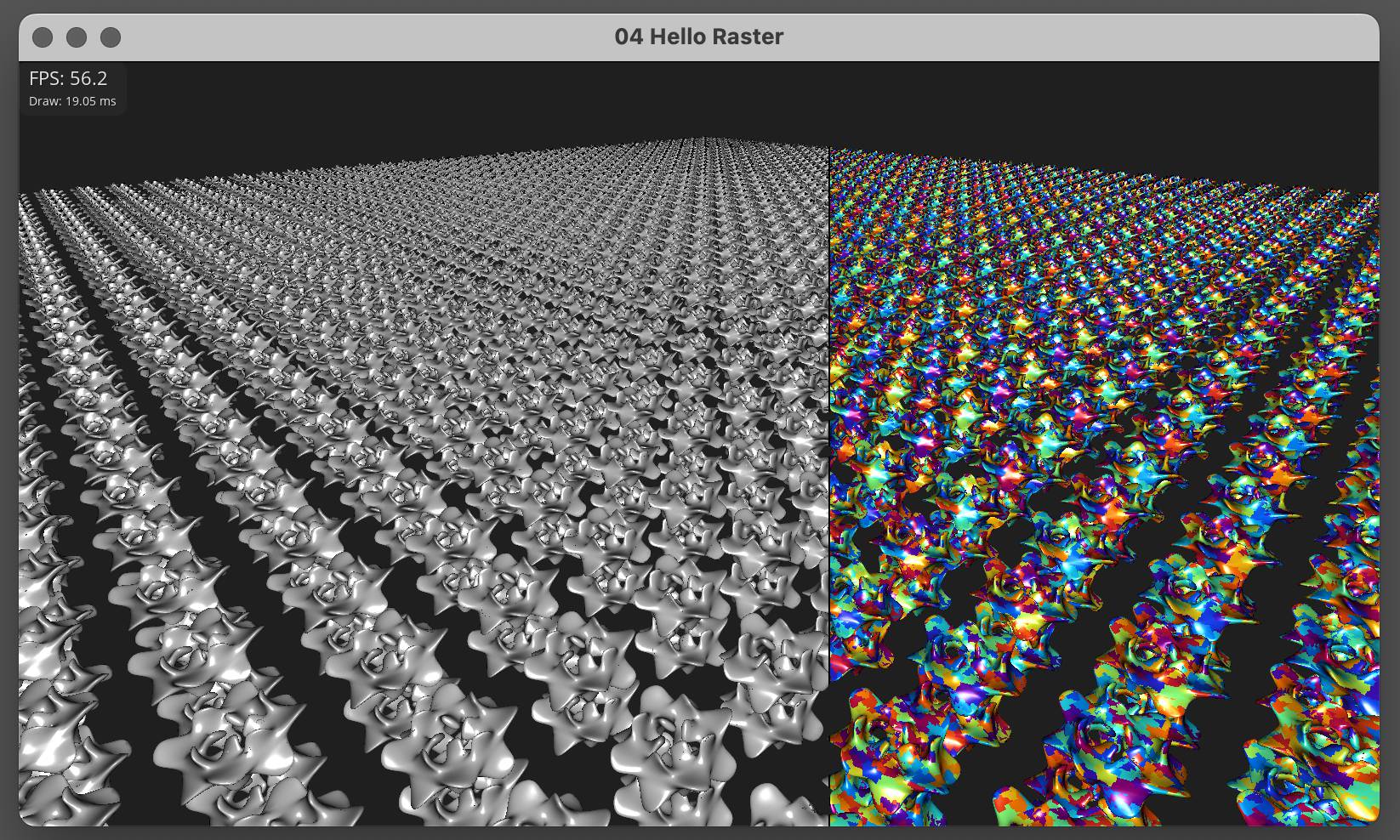
We chose Buffer over Texture for the depth surface due to the absence of atomic image operations in WebGPU. Click on the image to open the WebGPU build. There is minor flickering caused by non-atomic color writes, but when using combined 64-bit atomic depth-color writes, the result is artifact-free:
This and many other examples are available in our Tellusim Core SDK.